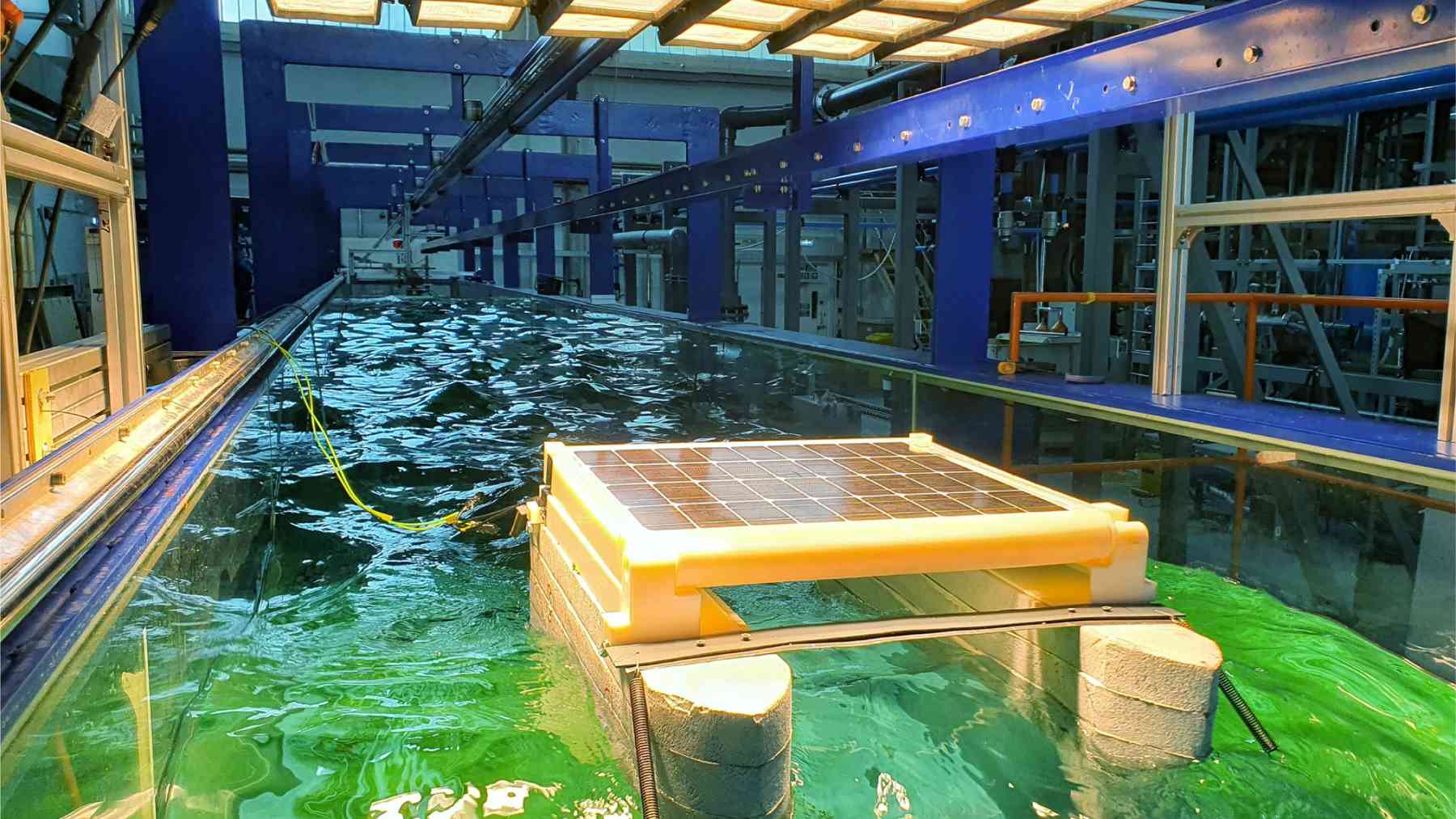
A concrete channel 98 feet long and 5 feet wide, filled with fresh water to a depth of 5 feet.
Three paddles at one end, a sloped beach at the other, and 21 halogen lamps hanging overhead.
Floating under them, one 50 watt panel on a pair of foam hulls, moored at four points.
The waves are two inches high.
The number travelled a long way.
Half a percent, by the cosine
A flat panel lit from directly above collects the most light it can. Tip it, and the lit area shrinks by the cosine of the angle, which is the oldest arithmetic in solar.
That function is almost flat near zero. At 6.7 degrees the cosine is 0.993, so the geometric loss is about 0.7 percent.
Average it over a panel that rocks back and forth through that angle rather than sitting at it, and the figure drops to roughly a quarter of a percent.
So a tilt of under seven degrees cannot, by itself, remove an eighth of the output. The measurement and the explanation have to come apart somewhere.
Where they come apart is the interesting part, and the authors say so themselves rather than hiding it.
The cosine gives a fraction of a percent. The tank gave 12.7.
Ten runs in a 98 foot tank
The wave tank is a flume at a British university with a solar simulator built above it, 21 lamps of 500 watts each in a grid.
The panel is a 50 watt monocrystalline module on a catamaran of extruded polystyrene, with the whole structure about 3 feet long. In still water the lamps were trimmed so it produced 30 watts, and that became the baseline.
Ten wave conditions were run. Two heights, 2 inches and 4 inches, crossed with five frequencies from 1.0 hertz down to 0.8.
Those frequencies gave wavelengths of roughly 5.1 to 8 feet. Every run was repeated three times, and the repeats matched.
The worst case was the 4 inch wave at 0.95 hertz, a wavelength near 5.7 feet. There the panel lost 12.7 percent and its pitch amplitude reached 6.7 degrees.
Two heights times five frequencies. Thirty watts as the baseline.
Six point seven degrees, and a sine
The authors noticed that their losses tracked the pitch angle closely, and proposed a formula. Loss equals the sine of the pitch angle.
Sine, not cosine. At 6.7 degrees the sine is 0.117, which lands near the 12.7 percent they measured, and the fit holds across most of the ten cases.
They label it a hypothesis, derive it from those ten runs, and note that one case misses badly. That is honest reporting of an empirical curve fit.
What the paper does not do is explain why a sine should govern this. There is no optical argument for it, and sine and cosine behave in opposite ways near zero.
Also worth noting: 6.7 degrees is the amplitude, so the panel swings from minus 6.7 to plus 6.7, a full travel of 13.4 degrees.
Ten data points behind the curve. One case off by a lot.
Four inches of wave, not forty
The gap between this flume and the open sea is the limit the authors flag hardest. Their waves were, in their own words, generally smaller than those in real seas.
A 4 inch wave with a 5.7 foot wavelength is not a scaled version of an Atlantic swell. It is a ripple, and the paper offers no scaling law, no model ratio and no Froude number to bridge the two.
Their reading of that gap is that real motions would be larger and the losses therefore worse. That is plausible and it is also an assumption.
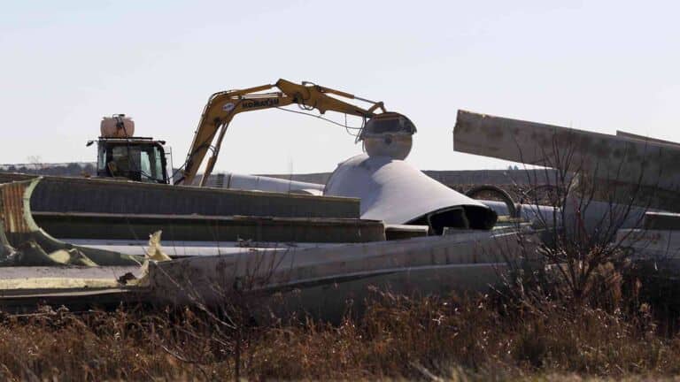
What an installation meets in open water is a different order of problem, as one plant that suddenly collapsed demonstrated.
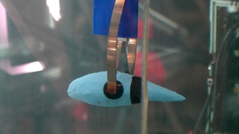
Even the undersides change, with divers counting 543 mussels for every square foot on floats sited offshore.
Four inches in the tank. Something else in the water.
One panel, no breakwater, regular waves
Three limits sit on this result and all three are stated in the paper. The waves were regular rather than irregular, which no sea is.
Only one panel was tested, so nothing here covers how a connected array shades itself as the units move out of step.
And no breakwater was ever in the tank. It appears in the discussion as a concept that could reduce the loss, with a claim that the extra cost would not be significant. Neither was measured here.
None of that makes the experiment weak. It makes it early, which is what an experimental paper with ten runs is supposed to be.
The tank, the ten cases and the formula are published in the paper.
The same work is open access through the journal.
The wave tank produced a clean number, and what still has no physical explanation is why the angle should cost twenty times the optics.
Read the whole thing?
Get the week's signal, not the noise
Our sharpest reporting on energy, climate and nature — free, once a week.